


Supervisory Control & data adquisition systems
- Products
- Master Stations
- Controls
- UTR´s
Supervisory Control & data adquisition systems
Master Station
- SCADAPAC XAR2-D
- SCADAPAC XAR4-DE

Comunication front end processors
- SCADAPAC CIC XAR2/4
- SCADAPAC CIC XAR4/6
Remote Terminal Units
- SCADAPAC XAR1-M (Subestaciones)
- SCADAPAC XAR1U (Tableros)
- SCADAPAC XAR1-P (Poste)
SCADAPAC XAR4-DE
Supervisory control system with monitoring, telecontrol, telemetering, electric network automation and system management functions.
This device guarranties process telecontrol through any of the servers or operation terminals. This is achieved using a LAN Ethernet IEEE 802.3 , connected to a front end processor.
The acquired information from remote modules is processed by the front end processor and retransmitted to every node in the network.
The SCADAPAC XAR 2-D system works with two paralell servers, guarrantying the system’s redundancy.
Also it has a information terminal for engineering exploitation, system management, statistics etc.
The man-machine interface (MMI) is programmed using a OSF MOTIF with windows environment.
Additionally to traditional SCADA functions, SCADAPAC XAR 2-D can perform the following:
-ELECTRICAL NETWORK AUTOMATION
-GIS SYSTEM CONNECTION
-PLC FUNCTIONS
-ENGINEERING TERMINAL
-MANAGEMENT SERVER
-SAP-R3 SYSTEM CONNECTION
-INTELLIGENT PHONE COMMUTER
-REMOTE DIAGNOSTICS VIA PHONE LINE
-REMOTE DIAGNOSTICS VIA INTRA OR INTERNET.
-MAINTENANCE MODULES
-MONITOR AND CONTROL OF SUBSTATION AUTOMATION SYSTEMS
-WAN CONNECTION
GENERAL DESCRIPTION.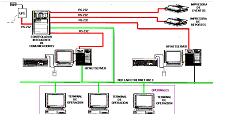
The SCADAPAC XAR 2-D is part of a series of automation products developed by Eseam, Inc. based on open architectures for software and hardware platforms.
Our core technology is based on HP computer equipment and Motorola Computer Group’s embedded boards for the different kinds of front end processors.
1.- HARDWARE ARCHITECTURE
Communications run through a LAN Ethernet, keyboard, printers and UPS.
2.- SOFTWARE ARCHITECTURE 
The programming structure of the software is divided into three great blocks.
Each of these blocks represent the application and function level of each software module that comprise the entire MMI.
The core of each of this layers is UNIX or Windows according to user´s requirement.
The system’s phylosophy comprises different programming modules that act independently and perform their links to the rest of the system through a relational data base and the different routines on the operative system.
THE THREE BLOCKS ARE:
- The first block of the sytem constitutes the basic programming modules, fundamental for the system’s operation.
-data base
-SCADA program
-communication module
-diagram editor
-function and report management
-system monitoring
-The second block comprises the man-machine interface configuration.
-diagram creation
-report creation
-panel creation
-screen personalization
-function personalization
-logger management
-trend and statistics management
The third and last block of the system, is comprised by the applications that personalize and are specific to the system involved, they could be:
-distribution
-transmission
-generation
Some examples of specific application modules are:
-automatic generation control
-overload drain
-distribution network automation
-ied setting changes
-economic dispatch
-load flow
-voltage flow conrtrol
-post-mortem analysis
-ied oscillography
-down-time management
-submaster module
-maintenance modules
-configuration and control of intelligent phone line commutter
3.- MAN MACHINE INTERFACE
Using different software modules, an information explotation structure was created. It defines the profile of the different MMI users:
-maintenance personnel
-control personnel
-substation personnel
-communications personnel
-operators
The block diagram looks like this:
These different operation modes, gather all required functions for the optimum exploitation of the system’s information. Starting with the basic SCADA and protection functions up to IED settings changes and oscillography downloads done from any terminal.
Every module has a security level access and will require a password to enter.
OPERATOR GUIDE (GAS)
-substation diagrams
-alarm reports
-indication tables
-metering tables
-fault reports
-commandss
-operation draft management
OPERATION RESULTS ANALYSIS (OAS).
-event logger
-event sequence
-calculated variables
-limit violation
-historic trends
-operation log-books
-hourly metering
-affected loads
-downtime
-operation statistics
-load balances
-loss analysis
-service quality analysis
-armonic percentage
-energy balance
FAULT ANALYSIS (FAS)
-station’s diagrams
-protection diagrams
-fault locator
-fault statistics
-oscillography
-post-mortem analysis
-relay diagnostics
-logic sequence editor
-logic sequence enable
-economic results analysis
MAINTENANCE MANAGEMENT (MAS )
-operation statistics
-real time status i2t
-remaining life calculation
-equipment data (data base)
-maintenence log-book
-preventive maintenance planning
-draft follow-up
-annual maintenence programs
-work orders
-maintenance procedures log
-maintenance cost evaluation
EXPANSION AND MANAGEMENT (EAS )
- System synopsis
- Data base configuration
- Communication settings
- Communication statistics
- Setting logger
- Diagnostics tools
- Auto diagnosis reports
- Report editor
- Time synchronizing tools
- Submaster function configuration
- Superior level configuration
- LAN knot installation
- WAN connection configuration
Grouping functions according to the different user’s needs, makes it possible to gather and display the information that each user specificly needs.
4-EXAMPLE OF A DISPLAYED SCREEN ON THE MMI

SCADAPAC CIC XAR2/4
Compact Communication Controller Equipment that manages a wide range of communication protocols either standard or proprietary.
Insures full connectivity to any Protection, Automation and Control equipment with Lan Ethernet and Superior Level networks.
It transfers information to a local console through a Lan IEEE 802.3 and to the Superior Level Control Center via Modem, Radio-Modem, Microwave System, Power Line Carrier, etc.
Monitoring communication telegrams in the selected protocol, can be done using the RS232 port exclusively utilized for monitoring and configuration. Communication diagnosis and determination of kinds of errors can be obtained through this port. Also a real time event logger is automatically available.
Monitoring the Data Base makes equipment status available at all times.
Real time reading and modifying of the Data Base, table transfers, point selecting and grouping (considered virtual RTU data), can be sent to Superior Levels.
It allows timing settings for pre and post transmission and adjustable timing for repeater applications on the different protocols installed.
It is a Communication Controller and Protocol Translator in the same piece of equipment.
The SCADAPAC-CIC XAR 2/4 is part of a family of products manufactured under the Integrated System concept. It’s functionality and performance under severe conditions make it highly reliable in Substation Automation applications.
1- ARCHITECTURE
Each SCADAPAC-CIC XAR 2/4 is dimensioned according to the specific characteristics of each system.
Each board that integrates the CPU is designed to withstand industrial environments.
The different SCADAPAC-CIC XAR 2/4 models can be delivered with RS232, RS485 or both ports; expandability is possible to a maximum of 32 channels increasing by two at a time.
2- CONNECTIVITY
SCADAPAC-CIC XAR 2/4 is in charge of acquiring data from the systems coded on TCP/IP. Then it transmits them to Superior Level in the protocol required by the Master Station.
Physical connection for radio communication can be done in two or four strings. To connect ports RS422 and RS232 we use a standard configuration DB-9 connector.
3- BUILT IN CLOCK SYNCHRONIZATION
SCADAPAC-CIC XAR 2/4 can synchronize its built in clock through Lan network given the instruction from the local console, or through TCP/IP if the instructions come from the Master Station or a remote console.
Time can also be synchronized through an IRIG-B interface via satellite using GPS equipment.
4- SUB MASTER
SCADAPAC-CIC XAR 2/4 can communicate with RTUs from other manufacturers. It can be configured as a Sub Master to control several RTUs. i.e. pole RTUs, water well RTUs, remote modules from different manufacturers, etc.
When configured as a Sub Master, and communications on any channel should fail the SCADAPAC-CIC XAR 2/4 will ask the inferior module the same question a determined number of times. If it does not get an answer, it skips that module during the next scan unblocking the channel that is not working properly.
5- BACK-UP
SCADAPAC-CIC XAR 2/4 has the option of configuring a Main and a Back-up communication port.
Hot Standby redundant communication channel is made available, each time the back-up communication port is used.
6- PROTOCOLS
The equipment can operate with different protocols at the same time and/or several protocols of the same kind. Some of the main protocols SCADAPAC-CIC XAR 2/4 manages are:
- SCADAPAC V5.0
- DNP3.0
- HARRIS 5000/6000
- LEEDS & NORTHRUP
- LANDIS & GYR
- CDC
- WESTON RECON 1, II
- FUJI
- INDACTIC
- MODBUS +
- MMS
It also has capability of configuration of multiple addresses for each protocol.
The mentioned protocols can be managed in a master or remote configuration. In the master mode, scanning is made by the SCADAPAC-CIC XAR 2/4. In the remote mode, it responds to the scanning from Superior Level equipment.
CPU SPECIFICATIONS
- CPU Intel Pentium
- From 4 MB to 64 MB RAM
- From 16 MB to 1 GB Flash Disk
- RS-232 Maintenance port
- RS232/422/485 Interconnected port
- Ethernet Interconnected port
POWER SUPPLY
- Input voltages: 24, 48, 125 or 250 VDC: 127 or 240 VAC (60 Hz).
- Output voltages +5 VCD (0.75 to 7 A), +12 VCD (0-1 A), -12 VCD (0-0.3A).
ENVIRONMENTAL
Operation Temperatures: 10 to 70º C
Relative humidity: 0 to 95% not condensed
SPECIFICATIONS
SWC ANSI/IEEE C37.90 1-1989 (5 Kv).
Surge Protection: (5 Kv), IEC 255-4
UTR
 |
 |
 |
 |
 |