


Sistema Integral para Automatización de Subestaciones
- Productos
- Módulos SIMPAC
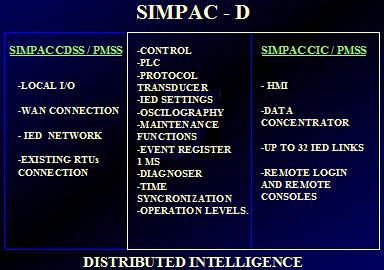
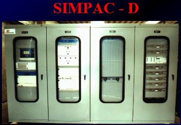
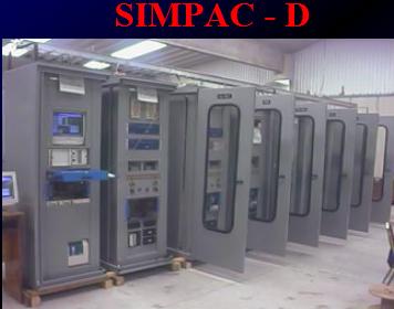
- SIMPAC-D
- SIMPAC-T
- SISIPAC
Sistema Integral para Automatización de Subestaciones
Sistemas Remotos ( SSR's ) SIMPAC XAR1-M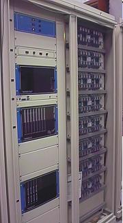
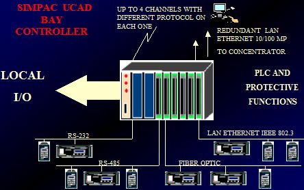
- SIMPAC UCAD
- SIMPAC CIC XAR2/4
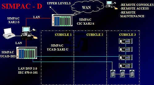
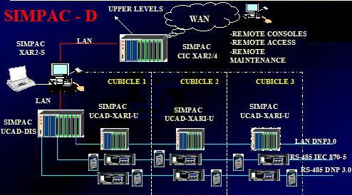
Sistema SIMPAC D para automatización de Subestaciones de Distribución
- SIMPAC - UCAD
- SIMPAC CIC XAR2/4
- SIMPAC - CIC - XAR2/6
- SIMPAC XAR2 - S
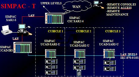
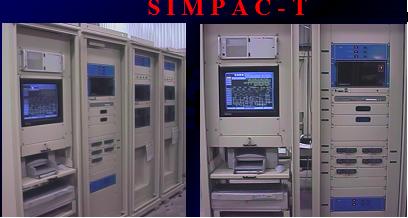
Sistema SIMPAC T para automatización de Subestaciones de Transmisión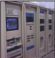
- SIMPAC - UCAD
- SIMPAC CIC XAR2/4
- SIMPAC - CIC - XAR2/6
- SIMPAC XAR2 - S
| Download Document | |
| Descripción Proyecto SICLE / SIMPAC T | |
| Terminación Proyecto SICLE / SIMPAC T | |
| Subestaciones de CFE México equipadas con equipos SIMPAC T |
Los Módulos de Control y Adquisición de Datos modelos SIMPAC, ofrecidos son de última tecnología, con un alto espectro de opciones de conectividad, de probada eficiencia y alta confiabilidad en el campo de las aplicaciones energéticas para las cuales fueron específicamente diseñados con las siguientes características generales:
- Basados en BUS PC-104 PLUS
- Gabinete 6 U para montaje en rack de 19” o montaje en panel.
- Con capacidad de expansión modular.
- Basado en procesador Pentium II @ 266 MHz con 64 Mb de memoria RAM, de 32 bits .
- Equipado con 1 puerto RS-232 para mantenimiento, configuración y diagnostico accesible por medio de password.
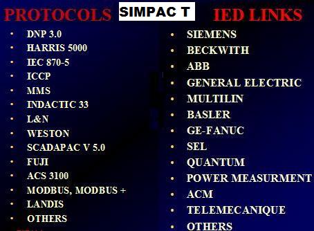
- Equipado con 4 puertos serie RS-232/RS-485 para comunicación con protocolo DNP3.0 clase 2 / 3, HARRIS 5000/6000 y SCADAPAC V5.0 con velocidades de transmisión configurables en todos sus parámetros con la posibilidad de operar a velocidades desde 150 a 38400 BPS.
Equipado con 3 puertos RS-232/RS485 para conexión de DEI´s configurables en todos sus parámetros con la posibilidad de operar a velocidades desde 150 a 38400 BPS, con manejo de protocolo DNP 3.0 nivel 2 / 3 , protocolos de comunicación con DEI´s familia SEL (121, 221, 321, 421, 167, 267, 367, 251, 351, 501, 387), Multimedidores GPI (OPH3V9, K4000), RIS (TR1625, TR1692C), IEC870 configurables por el usuario en cualquiera de ellos con cualquiera de los 3 puertos, manejando el acceso a los DEI´s con la aplicación completa de fabricante, así como la funcionalidad de puerto transparente, compatible 100% con el equipo SICLE ya existente. El tiempo de refresh de las variables analógicas es configurable, y de acuerdo al tiempo que sea solicitado según su importancia puede ser cada 50 milisegundo, segundo, minuto o se puede configurar su barrido hasta 1 hora y para las variables digitales es configurable su barrido adquiriendo la información cada 150 milisegundos, minutos y horas estampando la resolución de 1 milisegundo de acuerdo a la información original adquirida por el dispositivo electrónico.
- 1 (una) Fuente de poder redundante con entradas de 125 VCD +/- 15% principal ( en su entrada ) y 127 VCA +/- 15% ( en su entrada )de respaldo, con switcheo instantáneo con alarmas de señalización de fuera de rango de +/- 15% mediante Led´s, con señalización por contactos secos tipo “C” de falla de fuente DC y AC, con restablecimiento automático, cuenta con protección de fusible y switch de encendido, protecciones contra transitorios e inducciones, esta dimensionada para soportar 10% mas de carga por un tiempo indefinido de la capacidad total con toda la funcionalidad.
- Puerto paralelo para impresora de eventos (SOE) incluido.
- El equipo tiene la facilidad de comunicación al SICLE existente mediante RED Lan Ethernet IEEE 802.3 O puertos serie RS-232 con protocolo SCADAPAC V5.0, HARRIS 5000/6000 o DNP 3.0 NIVEL 2 /3 compatible al 100% con toda la funcionalidad del SICLE instalado.
- La comunicación entre MCAD´S y entre servidor Scada y MCAD´S es mediante una arquitectura que garantiza el intercambio de variables adquiridos de campo manejando interlocks cruzados, ya sea por medio de protocolo propietario SCADAPAC V5.0 o mediante DNP3.0, manejando una red separada dentro de cada sección del tablero.
- Redundancia en Red tipo anillo
Módulo de entradas digitales
- Capacidad del módulo de 48 entradas digitales a 125 VCD con aislamiento óptico de 1500 Vrms
- Cada entrada digital es configurable como tipo estado con memoria DCM, acumulador de pulsos y/o secuencia de eventos (SOE), todos los anteriores seleccionables por software por el usuario por punto individual.
- La función de secuencia de eventos SOE tiene una resolución de 1 milisegundo.
- Cada entrada digital es seleccionado por el usuario por software para la habilitación del filtro antirrebote (debounce) y en caso de habilitarlo es seleccionable en un intervalo de 8 ms a 100 ms, ajustable por software en todo el intervalo.
- Tiene capacidad de configuración por cada punto individual, el tipo de contacto que se va a conectar con lógica positiva o lógica negativa (Tipo A o Tipo B) es seleccionable por el usuario.
- Cada entrada digital tiene señalización luminosa (por led frontal) que indica el estado en que se encuentra.
- Todos los cambios de estado tiene estampado de fecha con formato dd/mm/aa (dia / mes / año) y con formato de tiempo HH(0-24) MMSSmm (Hora, minutos, segundos y milisegundos).
- Con capacidad de almacenamiento de 4096 eventos mínimo.
- Con capacidad de almacenamiento de 8,192 pulsos mínimo de cada acumulador y todos los puntos pueden ser configurados.
- En caso de perder la comunicación con el equipo instalado, almacena todos los cambios y acumuladores, en cuanto se reestablece la comunicación los envía con registro de fecha, hora, minuto, segundo y milisegundo.
- Las entradas son aisladas con protecciones contra transitorios e inducciones por medio de arreglos de varistores y con su respectivo optoacoplador.
Módulo de entradas analogicas
- Capacidad del módulo entradas analógicas aisladas con 3 TP´S y 3 TC´S
- Entradas analógicas de TP´s de 0 -69VCA nominales para medición instantánea
- Entradas analógicas de TC´s de 0-5A nominales para medición instantánea
- Las entradas de TC´S Y TP´S están disponibles para la elaboración de secuencias de PLC y envió de información a la estación maestra.
- Capacidad de soportar hasta 15 Amperes y 400 A por 0.5 segundos/Hr. Y una sobrecarga de hasta 200VCA.
Módulo de salidas digitales
- Capacidad del módulo de 16 salidas de control momentáneos Abrir / cerrar mediante relevadores con capacidad de contacto de 125 VCD @ 10 Amp., y capacidad de manejo de mandos tipo latch (set / reset) mediante relevador con capacidad de contacto de 125 VCD @ 5 Amp. aislamiento óptico de 1500 Vrms por medio de contactos secos tipo C
- Todos los relevadores están protegidos individualmente contra operaciones involuntarias.
- El cierre de los contactos de salida de los controles momentáneos es configurable por punto (individualmente) entre 0.1 seg y 1 seg en pasos de 0.05 segundos seleccionables por el usuario, aislamiento óptico de 1500 Vrms por medio de contactos secos tipos A y B.
- El sistema contempla mecanismos para determinar la integridad de la bobina de los relevadores de control, además de ello el estado de la bobina se reporta al Servidor Scada y se incluye la indicación visual correspondiente.
- Cuenta con protección por hardware y software para que las salidas no actúen en caso de falla de alimentación, transitorios, encendido o apagado del equipo.
- Las salidas solo actúan con el envió de un comando y están respaldadas por la función de CHECK BEFORE OPERATE.
- Soporta pruebas SWC y dieléctricas según la especificación CFE U000-11.
Software y mímico procesado
- Software y mímico microprocesado que despliega los eventos ocurridos con resolución de 1 milisegundo, diagrama unificar de la bahía, estados del interruptor, cuchillas y mediciones. Con acceso mediante niveles de password, de cristal liquido, Alta seguridad en la ejecución de controles confirmando inicialmente el password y posteriormente la selección y la operación.
- El sistema operativo Multimaster es un sistema operativo en tiempo real que cumple con todas las características de los mismos y esta basado en una plataforma que garantiza esta funcionalidad.
- Función de PLC con capacidad de 48 variable digitales, 3 TC´S y 3 TP´S de variables analógicas y 16 salidas de control.
- Con capacidad de soportar un mínimo de 128 temporizadores, 128 banderas y 128 contadores.
- Con capacidad de soportar un mínimo de 4000 instrucciones.
- Tiempo máximo de ejecución de 200 ms por cada 1000 instrucciones.
- Maneja lenguaje de escalera, relacional y bloques.
- Ejecuta funciones aritméticas, científicas, lógicas, de comparación, temporizadores, contadores, banderas y de loop.
- La totalidad de la base de datos puede ser utilizada como variables dentro de la programación.
- Soporta puntos de otros módulos ya instalados.
- Cuenta con el software para desarrollar las aplicaciones PLC desde el equipo ya instalado así como desde una PC con Windows 98.
- Cuenta con el software y hardware necesario para bajar los desarrollos de una PC al equipo.
- Todos los programas y variables que se manejan en el equipo están almacenados en memoria de estado sólido y tiene capacidad para soportar toda la funcionalidad (acumuladores, eventos con registro de fecha y hora, mediciones, PLC, todas las variables de futuros DEI´s, registradores etc... así como diagnósticos, sincronización de tiempo, local / remoto, etc) completa.
- Realiza la sincronización de tiempo por medio del comando de sincronización proveniente del protocolo DNP3.0 del equipo Sicle actualmente en operación.
- En caso de falla de comunicación mantiene el tiempo con una desviación menor a 0.5 seg en 24 HRS.
- Con capacidad para soportar una ampliación del 20%
- Con capacidad para efectuar la función de Submaestra
- Con capacidad de control local y remoto
- Cuenta con switch local remoto para la habilitación de los mandos y cumple con la funcionalidad local remoto del equipo SICLE instalado.
- Con capacidad de diagnostico interno y remoto
- Indicación visual mediante leeds en cada módulo
- Las tarjetas se extraen por el frente del gabinete y los cables de conexión son por la parte posterior de los módulos, los cables están 100% identificados con etiquetas indelebles.
- El suministro incluye todos los accesorios necesarios para el arranque, configuracion, modificación, actualización de software del equipo, adicionalmente cuenta con todos los periféricos e instrumentos necesarios para realizar las tareas descritas.
- Incluye puerto RS-232 para mantenimiento, configuracion, monitoreo y pruebas , accesible por medio de password, para conexión a equipo PC o LapTop por medio de hyperterminal, por este puerto es posible realizar toda clase de configuraciones, diagnósticos, programación , ajustes y pruebas del equipo.
CONECTIVIDAD
- El equipo ofertado se enlazara al equipo actualmente en operación por medio de protocolo de comunicación DNP3.0 / HARRIS 5000 o HARRIS 6000 seleccionables por software (en cualquier combinación) , por medio de 2 puertos serie RS-232 (Principal y Respaldo) configurables en sus velocidades de 300 a 38400 bauds.
- Se ofrecen 4 módems para la conectividad cumpliendo con las normas bell202,v.23,v.28, y v.32 (todas) .
LICENCIAS
- Los equipos se suministran con todo el software y licencias requeridas para la operación ,configuracion, mantenimiento, tienen una vigencia ilimitada , adicionalmente todo el hardware y el software están libres de problemas operación por cambios de fecha.
PERIFERICOS
- El equipo cuenta con switch local/remoto para la habilitación de los mandos.
- Tiene antena y receptor GPS para sincronización de tiempo. Tiene una exactitud de +/- 150ns.
- Salida un pulso por segundo y minuto BNC.
- Salida formatos IRIG B120 AM BNC y TTL BNC.
- Cable de conexión de antena a receptor de 30 metros de longitud.
- El receptor GPS tiene display y teclado para configuración.
- Es compatible con la tarjeta (TCI) instalada en el equipo sicle
 |
 |
 |
 |
 |
 |
 |
 |
 |
 |
 |
 |
 |
 |
 |
 |
 |
SISIPAC- General Description & functionality
1-ENTERPRISE-WIDE INTEGRATION SYSTEM
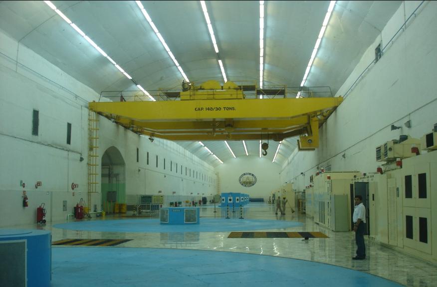
The management of electric utilities is based on a wide use of communication and  informatic systems for collection and process of real time data.That has been made available thanks to the improvement in new technologies, the multiplication of the use of IED’s, the progress in data communications and the arrival of new serial data protocols.During years, operation procedures, fault analysis and maintenance administration in electric substations have resulted difficult because of: the geographic distribution of the installations, unattended operation, reduction of the number of maintenance teams and operation teams.Nevertheless, substation automation systems have been developed in order to collect valuable information that most of the time is not delivered to the right destinations, for example: district, regional or national headquarters, where the specialists are located.
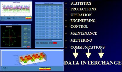
Based on that requirement, SEPAC offered to the electric utilities the new engineering and maintenance headquarter server: SIMPAC-SISIPAC, able to archive and to process historical data from different substations, in order to offer to the headquarters specialists tools such as: 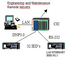
- real time snap shot of the equipments,
- strategies for predictive maintenance:
- On-line monitoring
- Outage planning
- Fault analysis
- Cost calculation
- Operation effectiveness analysis
The system is based in two principal events:
- The local gateway installed in each one of the substations.
The enterprise wide integration system software loaded in the headquarter servers.
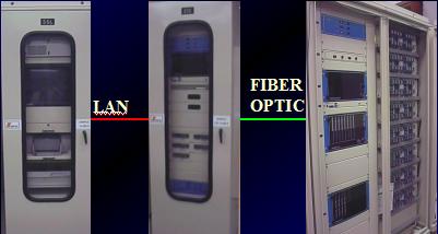
The server is based on a HP workstation computer that allocates all necessary software to monitor and control substation automation systems at regional or national level.
Using a SIMPAC CIC XAR2-4 front end communication processor, information is acquired from the IEDs and then transmitted locally and/or remotely to the engineering consoles.
Local access is done typically using a LAN Ethernet.
The CIC XAR2-4’s communication capabilities allow for remote reliable access through WAN, radio or other available means.
2. SUBSTATION GATEWAY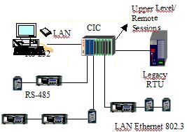
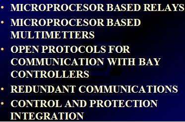
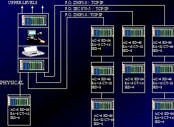
In the above architecture, the CIC-XAR2-4 becomes the heart of the system. It has the capability of managing up to 32 independent RS232 channels. Each channel can handle a different communication protocol, thus making it possible to access different brands of Protection Relays, multimeters or instrumentation devices. Another option for the basic architecture is building different communication networks. Each Network has a different communication protocol. IEDs with the same protocol can be connected on the same network in daisy chain.The CIC-XAR2-4 is also capable of accepting legacy RTUs if necessary in order to acquire digital I/O information for monitoring functions. That way, the system offers an attractive solution for the expansion of all legacy RTU’s. Taking in account that new IED are now available with Ethernet links, the CIC XRA2-4 has been developed to offer connectivity through LAN Ethernet IEEE 802.3.
Depending on the IED´s individual connectivity capabilities, equipment from the same OEM can be in a single RS-485 network or IED´s that have the same protocol can also be on the same network.
Depending on the user´s specifications and the time responses for SCADA applications, either array is possible. The system´s flexibility is an advantage for the user, for he can choose the most convenient way of connectign the devices.
The CIC is base on Motorola computer group´s embedded boards on a PC/104 Platform: pentium single board computer @ 350 MHz, 64 MB RAM. It has RS232/485 serial port for configuration, a parallel port to support a printer, keyboard jack & optional 3" floppy drive. A typical CIC-XAR2-4 Configuration is as follows:
- Power Supply
- Pentium processor board
- Watchdog board
- LAN board
- RS232 or RS485 boards
- IRIG-B connection jack
The CIC –XAR2-4 is configured and built to each system’s specific needs or user requirements, so optimal size is achieved, avoiding unnecessary “extra” hardware costs.
3 – SERVER SOFTWARE
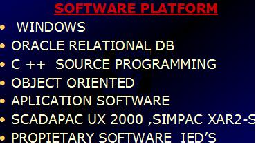
The system runs either under SCO-UNIX or Windows NT.
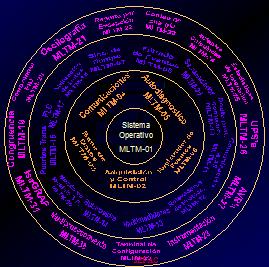
The programming structure of the software is divided into three blocks.
Each of these blocks represents the application and function level of each software module that comprises the entire engineering station.
The system’s philosophy comprises different programming modules that act independently and perform their links to the rest of the system through a relational data base and the different routines on the operative system.
These three blocks are: 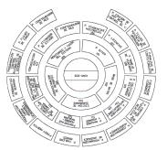
a) The first block of the system constitutes the basic programming modules, fundamental for the system’s operation.
-data base
-communication module
-diagram editor
-function and report management
-system monitoring
b)The second block comprises the man-machine interface configuration.
-diagram creation
-report creation
-panel creation
-screen personalization
-function personalization
-logger management
-trend and statistics management
c) The third and last block of the
system, is comprised by the applications that personalize and are specific to the system involved, they could be:
-operating parameters analysis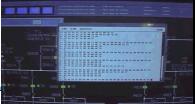
-overload cycles
-IED setting changes
-load flow
-voltage flow control
-fault information
-post-mortem analysis
-IED oscillography
-down-time management
-maintenance modules
-on- line monitoring
4- APPLICATIONS MODULES
a) THROUGH PORT
The Through Port function allows the user to access the protection Relay as if connecting directly with a Lap-top.
The system emulates the hyperterminal function and runs the licenced proprietary OEM software for each relay.
This function can be invoked either locally or remotely.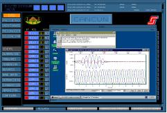
Setting adjustments, event register, metering, oscillography and all other information is obtained using the through port.
If the system is running under SCO-UNIX, a Windows session will be loaded. Then the proprietary software for the relay wanted will run on Windows.
The above example is the demo oscillography display for the SEL relays. All information is presented using the software developed for this use by the OEMs.
B) EXPOPAC: FAULT ANALYSIS SYSTEM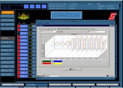
The ExpoPac software presents all the information available from any IED in the same format. Particulary, oscillography is displayed in a unique format, regardless of the Relay or Meter brand. This option is completely customizable as to the information that needs to be acquired.
Downloads can be done by setting a trigger if a certain variable reaches “x” value and/or by programming it on a timely basis and/or by operator request.
Also information to download is configurable. The operator can select which variables he needs to see, choosing from a wide range of different graphic displays.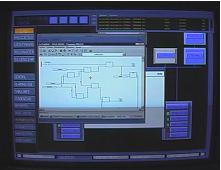
c) AUTOMATIC SEQUENCES
This is a powerful tool for simulation and analysis. The PLC ISAGraph functions allow the user to write automation sequences.
If a specific failure occurs, an automatic sequence can be written to change the settings of the protection relays parameters according to the new substation scheme. This can be done automatically or it can trigger a system alarm for a human decision.
d) ENERGY BALANCE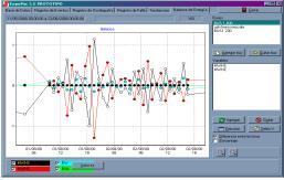
This analysis tool helps the user have an overview of the balance of energy in each substation or on the network.
This graphic environment helps visualize losses in the substation and efficiency of the transformation process under the different circumstances analyzed.
e) SEQUENCE OF EVENTS
The sequence of events has a 1 millisecond resolution.
Event display and acquisition is configurable by the user. Information can be acquired by exception, on a timely basis and/or by operator request. The information to be acquired is also configurable.
f) TREND GRAPHS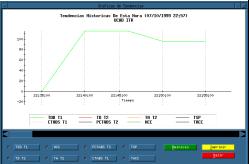
Another powerful monitoring and analysis tool. The graphs are also customizable, permitting the user to select the variables that are needed, the sample frequency and amount as well as the format to present them.
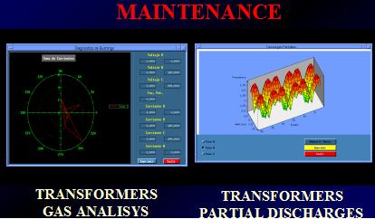
g) PREDICTIVE AND PREVENTIVE MAINTENANCE
SEPAC has developed software for monitoring transformers and breakers. These functions acquire information from the system’s data-base and instrumentation on field to provide information on equipment status. This is a tool used for predictive and preventive maintenance. It can print work orders and reports.
For transformers, besides the mandatory electric measurements, partial discharges, oil quality, bushings contamination and over-temperature cycles are monitored. Alarms and reports are configurable according to user’s needs.For breakers, I²T is calculated, as well as remaining duty life monitored for each pole. The system is then configured to alarm and report according to user’s specification or maintenance policies.The above example is a bushing sum of currents polar graphic. Graphs are also configurable to the user’s liking.
5- CONCLUSIONS 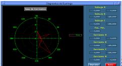
Enterprise wide data integration system gives new perspectives to run safely, economically and rationally the electric sector.
The data diffusion on headquarters networks, the availability of on line data extracted from substation automation systems,
the broadcasting of specific reports on web pages will have the following benefits:
Improvement in safety
Improvement in quality
Reduction in service interruption
Lower operation costs
Greater maintenance focus
Better management of assets
Increased longevity
Lower maintenance cost
Enterprise wide integration systems are nowadays a reality.
Electric utilities have this powerful tool available right now. Decision making and management will be better and better.
The concurrence will force sooner or later electric utilities to use this kind of systems in order to improve security and availability, and to reduce operation and maintenance costs.
SEPAC is proud to collaborate to this world wide effort, announcing its new engineering & maintenance headquarter server:
SIMPAC-SISIPAC
December 2007